
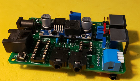
 Your board may look slightly different.
What are all these connectors?
You can think of the Nexus DR-X as the "Swiss Army Knife of Digital Radio Connections". There are more than a dozen connectors on your board.
So let's take a walk around the board and find out what each of them do. We will start in the upper right corner of your PCB and make our way clock-wise through them all.
Follow along below.
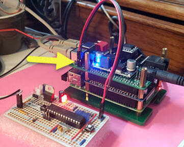
5 V and GND ...
You will find these two header pins in the corner of your board. They are simply there so that you can take advantage of the DC-DC Buck Converter power supply on the DR-X to run any home-brew project that you might be working on. They have nothing to do with our digital radios. I include these headers on every PCB I create.
In the photo you see here, I am powering my XYL-Switch. This circuit mutes the speaker on my 220 radio so that when my wife is annoyed with a radio talking in the shack when I am gone, she can push the white button to stop the chatter. One hour later the radio is back to normal.
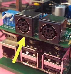
6 Pin Mini DIN Connectors ...
These two connectors are the main links to your radios. They are labeled "left" and "right." Because the sound card that we use to move audio in and out of our radios is stereo, we can run two transceivers at the same time.
The pin assignment on these connectors is standard and they should work with any radio that has matching connectors. Off the shelf cables should work fine here as long as all six of the connectors are wired. If your radio uses something else, you can make up a cable to match.
Here is a link to the DR-X Schematic where the pin layout is documented. Some digital radio interface devices require you to remove pin 6 from your DIN plugs when connecting to certain radios. That is never necessary here. Pin 6 on these connectors has no connection.
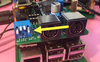
The Piano Switch ...
Unique to the DR-X is this set of fully programmable switches. Each switch is connected to its own GPIO pin on the Raspberry Pi. And each has its own pull-up resistor on the PCB. The logic is reversed, which means that flipping a switch down grounds the pin and pulls it low. There are sixteen different combinations.
We have made it easy for you to use these switches. Each time you boot up your Pi, there is a shell-script that reads the four GPIO pins and builds a simple string. In the photo switches 1 and 4 are down so that script will look for a script that you write named: "piano14.sh" If it is in your home directory, it launches it.
Testing Your Piano ...
Open a terminal window on your Pi and enter:
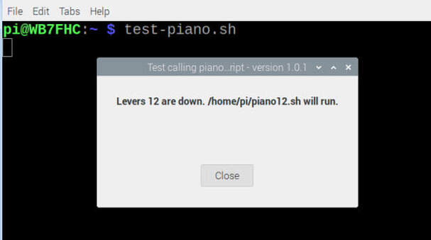
test-piano.sh
A box will appear and show you which levers are down. It also shows you the path and file name of the script you should write for that combination.
Some of you may have earier versions of the DigiLink that do not have the piano. You can still take advantage of this feature. Run the test anyway and you will see that the Pi finds a phantom piano with switches 1 and 2 down. If you write a script called "piano12.sh" it will launch automatically each time you boot up your Raspberry Pi.
You don't have to re-boot your Pi to test your script. In the terminal window enter:
check-piano.sh
TRRS Connector [right radio]...
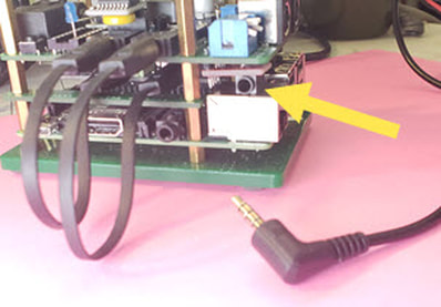
Tucked beneath the board, under the piano switch, is a TRRS jack. This connector's primary purpose is to be an alternate connection for the "right" radio. When in use, it takes the place of the right mini DIN connector. Some ham radios provide a mating connector for hooking up a head set with speaker, mic, PTT and ground.
TRRS stands for: Tip Ring Ring Sleeve. Notice the TRRS plug in the photo. This connector is directly linked to the 8 pin socket on the top of the board. You can place jumper wires in this header to patch your radio with the DR-X. But before you do so, there are traces on the other side of the board, under the header, that you will need to cut unless your radio is wired the same as the BTECH radios. If you are using a BTECH UV-2501 or UV-5001, you will not need any jumpers. An off the shelf TRRS jumper cable should get you right on the air.
TxAudio & RxAudio ...
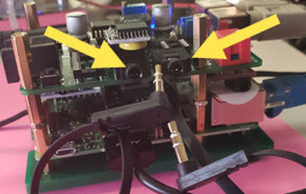
There are two stereo jacks on the front of the board. These are linked with 6 inch patch cables to similar jacks on the sound card which is in the stack under our board. This works like the phone patch of older days which is where the name Cross Patch comes from.
The first jack links to the stereo output and the left and right channels send audio to the left and right radios. The second jack is linked to the sound card's record channels and take audio from the left and right radios into the sound card.
Re-boot Button ...
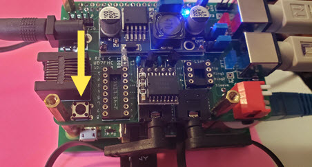
This little momentary switch can be used to safely re-boot or shut down your Pi. Hold the button down for a little over 2 seconds and the Pi will close all its programs and re-boot. Hold it down for over 5 seconds and the Pi will close all its programs and shut itself down. The clear acrylic top (not shown) has a hole directly above this button so that you can insert the eraser end of a pencil for easy access.
This little momentary switch can be used to safely re-boot or shut down your Pi. Hold the button down for a little over 2 seconds and the Pi will close all its programs and re-boot. Hold it down for over 5 seconds and the Pi will close all its programs and shut itself down. The clear acrylic top (not shown) has a hole directly above this button so that you can insert the eraser end of a pencil for easy access.
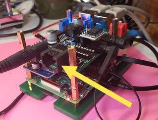
RJ-45 [left radio] ...
Don't confuse this one with the Ethernet connector on your Raspberry Pi. They are both RJ-45s. This 8 pin connector is connected directly to the left 8 pins of the 16 pin socket you see behind it in the photo above. Five of the other 8 pins are connected to pins on the left 6 pin mini DIN connector. This RJ-45 provides an alternate connection to your left radio.
Does this look familiar? It is compatible with a very popular digital radio interface that has been around for years. If you already have cables and jumpers for this other USB device, they will work here.
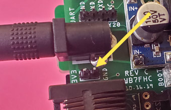
3V3 and GND Header ...
Like the 5 V and GND header explained above, these pins are here should you need 3.3 Volts..
Like the 5 V and GND header explained above, these pins are here should you need 3.3 Volts..
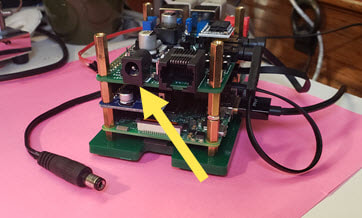
DC Power ...
This is a standard DC barrel connector. The size is 5 mm x 2.1 mm. Use anything from 9 VDC to 38 VDC. When you built your kit you set the output of the Buck Converter to 5.2 V.
When choosing your supply source make sure that it is rated for 2.5 Amps or more. Even though the voltage may be correct, if the current is weak your Pi will exhibit erratic behavior.
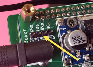
UART Connector ...
These pins are ready for you to plug in your favorite UART to USB cable. They allow you to access your Pi's terminal window from another computer.
These pins are ready for you to plug in your favorite UART to USB cable. They allow you to access your Pi's terminal window from another computer.
Discriminator Tap Jumpers ...
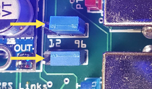
These two jumpers allow you to select which of the two audio input pins on the mini DIN go to the sound card. When placed on the 12 side, we get audio through pin 5 which is associated with the 1200 baud link on your radio. The photo shows the jumpers on the 96 side for nice clean audio right from the discriminator using pin 4. This is necessary for 9600 baud packet.
If your radio has a 9600 tap, always choose it no matter what mode and speed you are running.
The top jumper is for the right radio. The bottom is the left. They only work with radios attached to the mini DIN connectors.
RTC - Real Time Clock ...
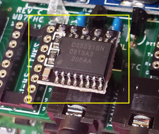
Perched above the RxAudio jack is the RTC Module. This Real Time Clock board with its own battery will set itself the first time your Raspberry Pi is connected to the internet. The Pi has no way of keeping time on its own so this little guy does the job for you.
Perched above the RxAudio jack is the RTC Module. This Real Time Clock board with its own battery will set itself the first time your Raspberry Pi is connected to the internet. The Pi has no way of keeping time on its own so this little guy does the job for you.